
Check out this course on Udemy here and get a discount on the advertised price!
With the recent release of Blender 2.8 the hugely anticipated and major iteration of the software, this huge milestone in its evolution is sure not to disappoint. There has never been a greater time to experience 3D software at its very best.
In the following post I outline the process of creating a 3D house model in Blender 2.8 from my latest course on Udemy. We first create 2D layouts and these can be used to begin modelling the mesh but in this course I render them to be used as reference images. One of the main goals of the course was to demonstrate some of the Arch-Viz and drafting tools available within Blender. These add-ons expand the functionality of Blender and can provide fast and efficient solutions to otherwise mundane tasks.
The first of these add-ons is called MeasureIt. MeasureIt provides the tools to dimension the mesh with linear, angle and arc dimensions. You can also add text labels, display the distance between objects and display the distance to the scene origin. This greatly expands Blender’s Arch Viz and drafting functionality with an easy to use interface.
Once the add-on has been enabled in user preferences, it will be displayed on the side bar within the 3D view (Short cut key N) and within the view tab. By default the MeasureIt tool is switched to hidden, simply click the “Show” button on the MeasureIt interface and the dimensions you create will be displayed in the 3D view. You can set up some basic text and styles properties in the configuration tab and have these added as the defaults.
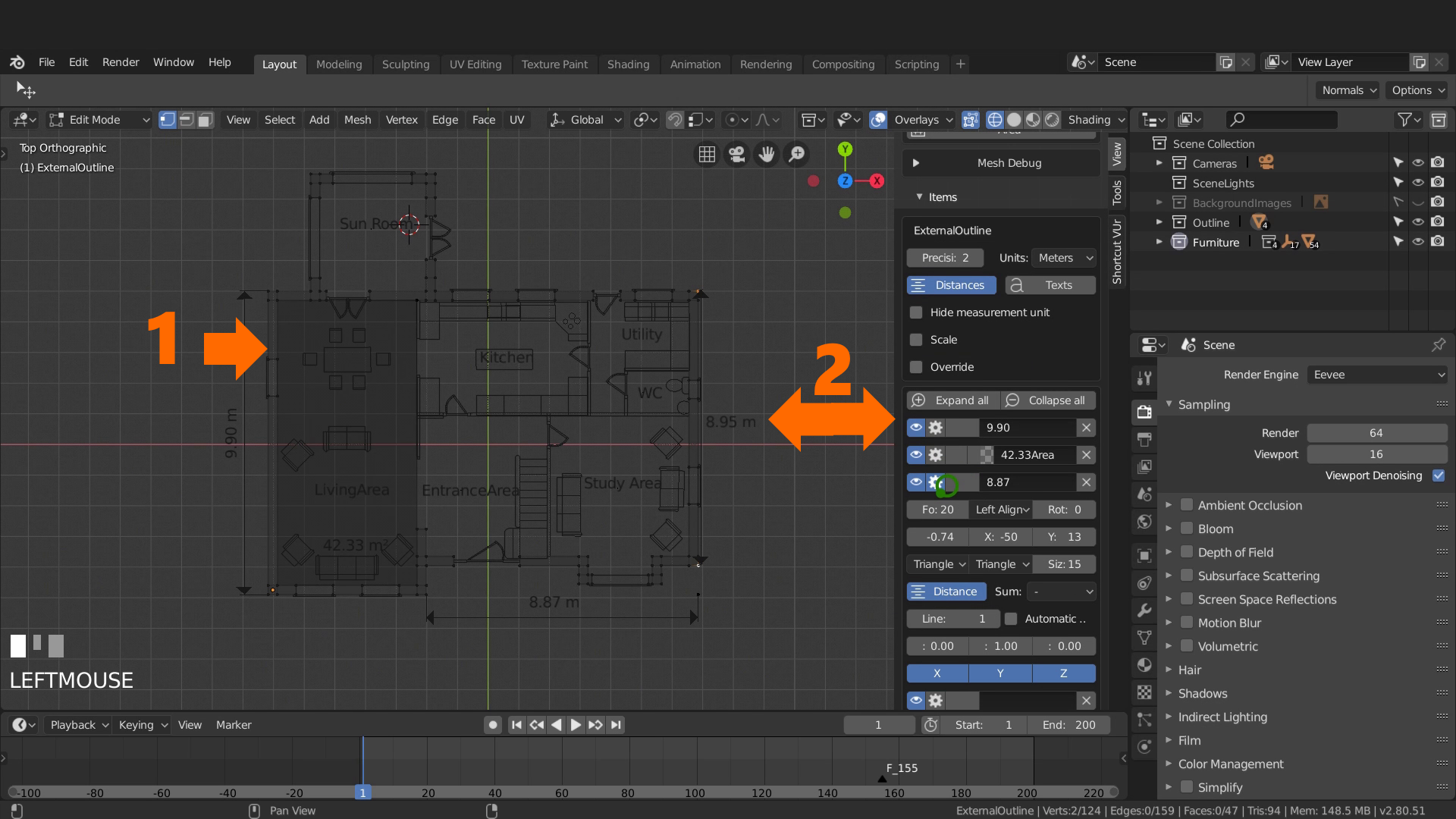
Adding a linear dimension simply involves tabbing into edit mode and selecting the two vertices you want that linear dimension to display the distance between.
For example once in edit mode and in vertex selection mode, shift select two vertices to get the distance between them. On the MeasureIt interface select segment to get a distance between these two points. Once segment has been selected additional properties for this measurement appear on the bottom section of the properties shelf (short cut key N). (See picture below)
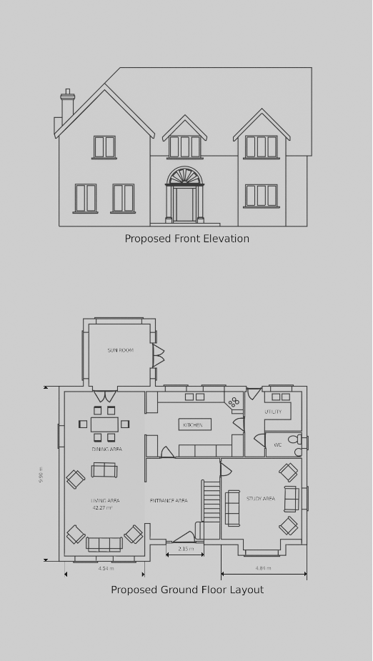
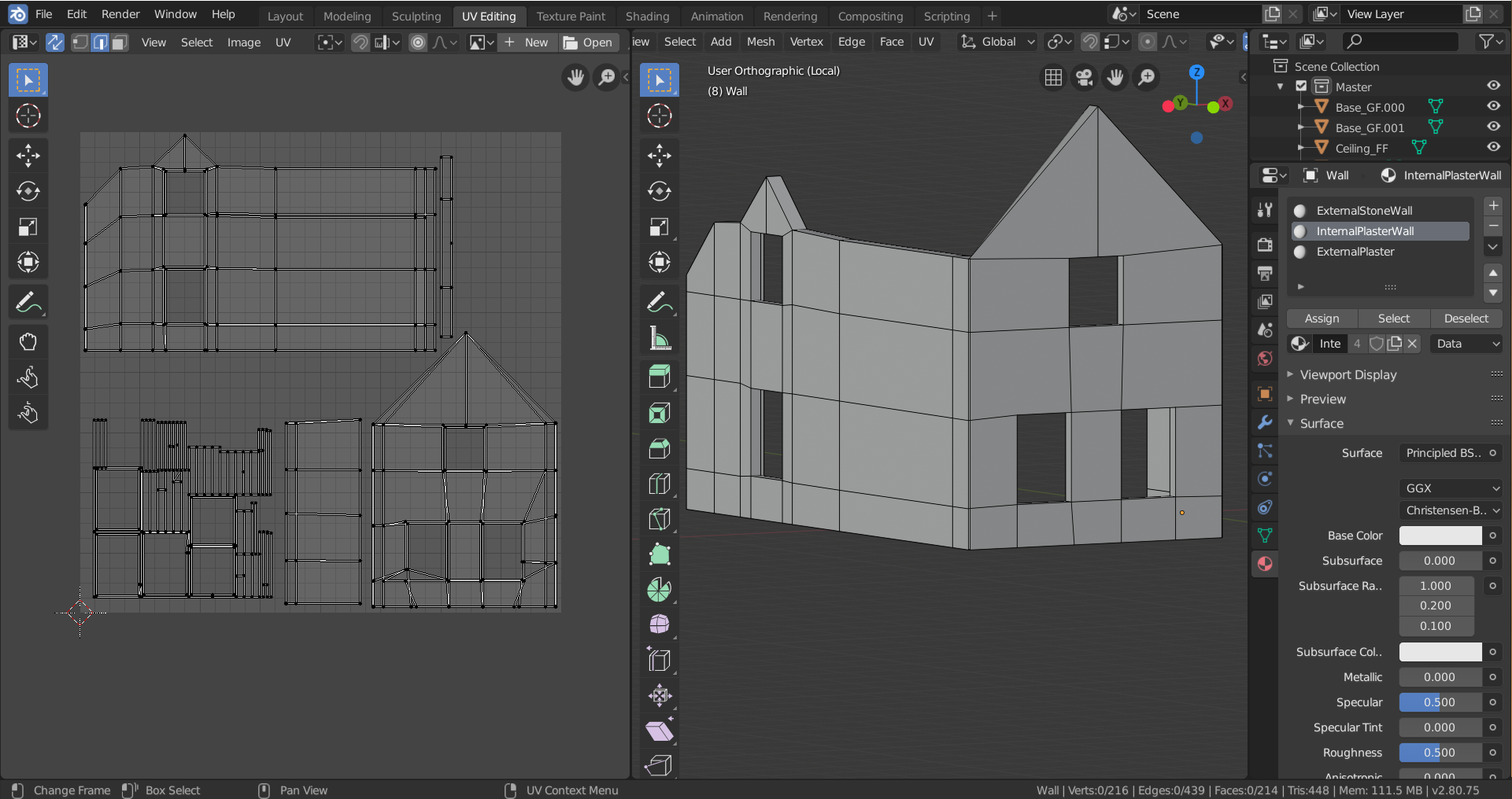
The image below was created by combining the MeasureIt dimensions, and an Eevee render of the mesh layouts. Blender has a built in line based non photo realistic rendering engine called freestyle. This render engine can create a hard line style that highlights the edge of the mesh, producing a technical drawn look. Having fully realized designs before committing to modelling can be time saving in the long run while also eliminating design and practicality issues at this stage.
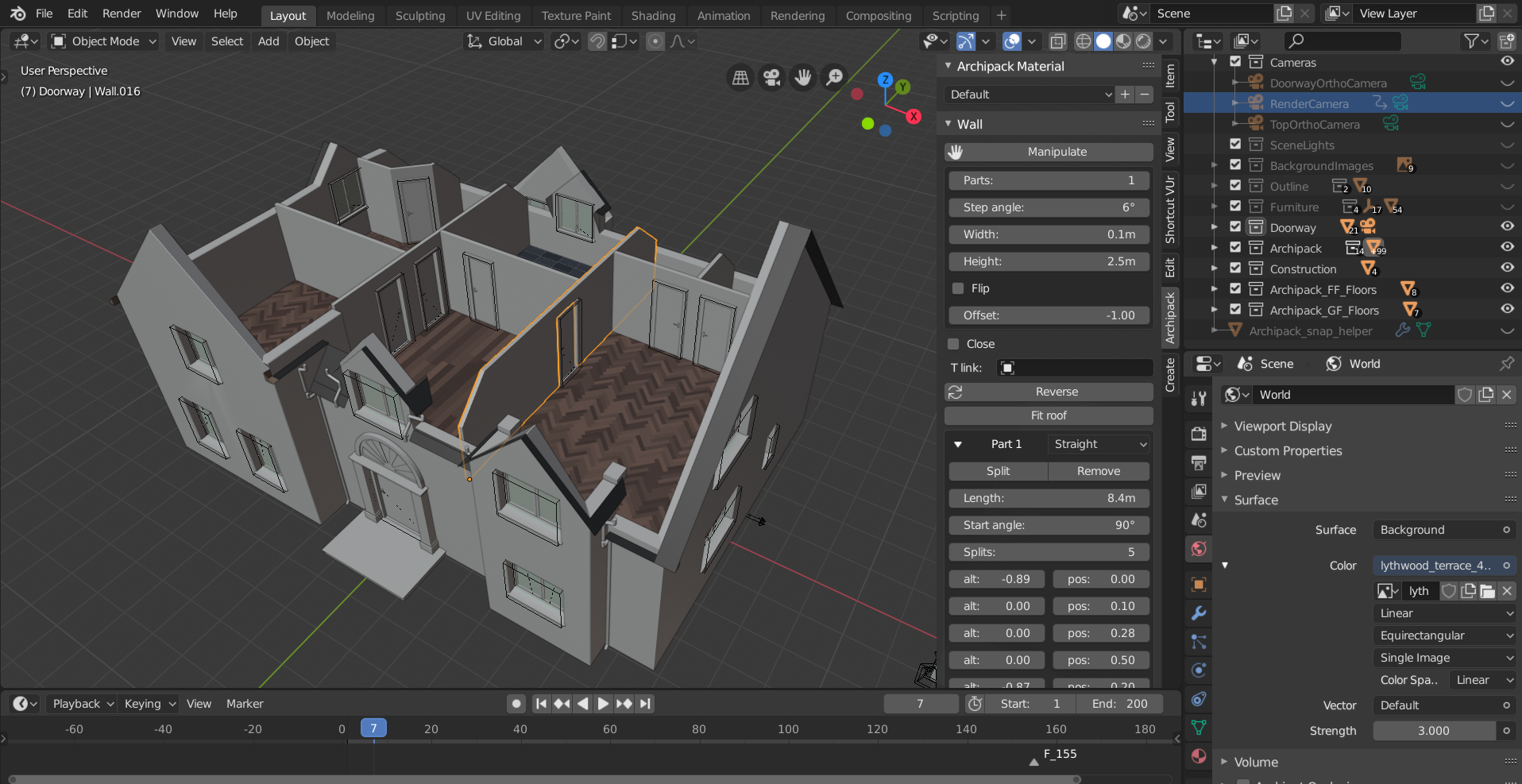
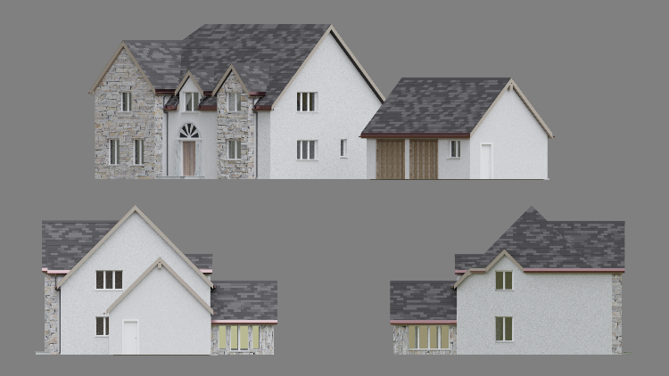
The next stage involves adding these images and using them as reference to 3D model the house. Add background or reference images from the add menu (Shift + A). Pictured below (2) shows the Archipack tab on the sidebar. From the create tab simply select any of the list architectural elements and they get added to the scene. Also pictured below are wall elements (1) that have been added then modified using the properties to match the reference images.

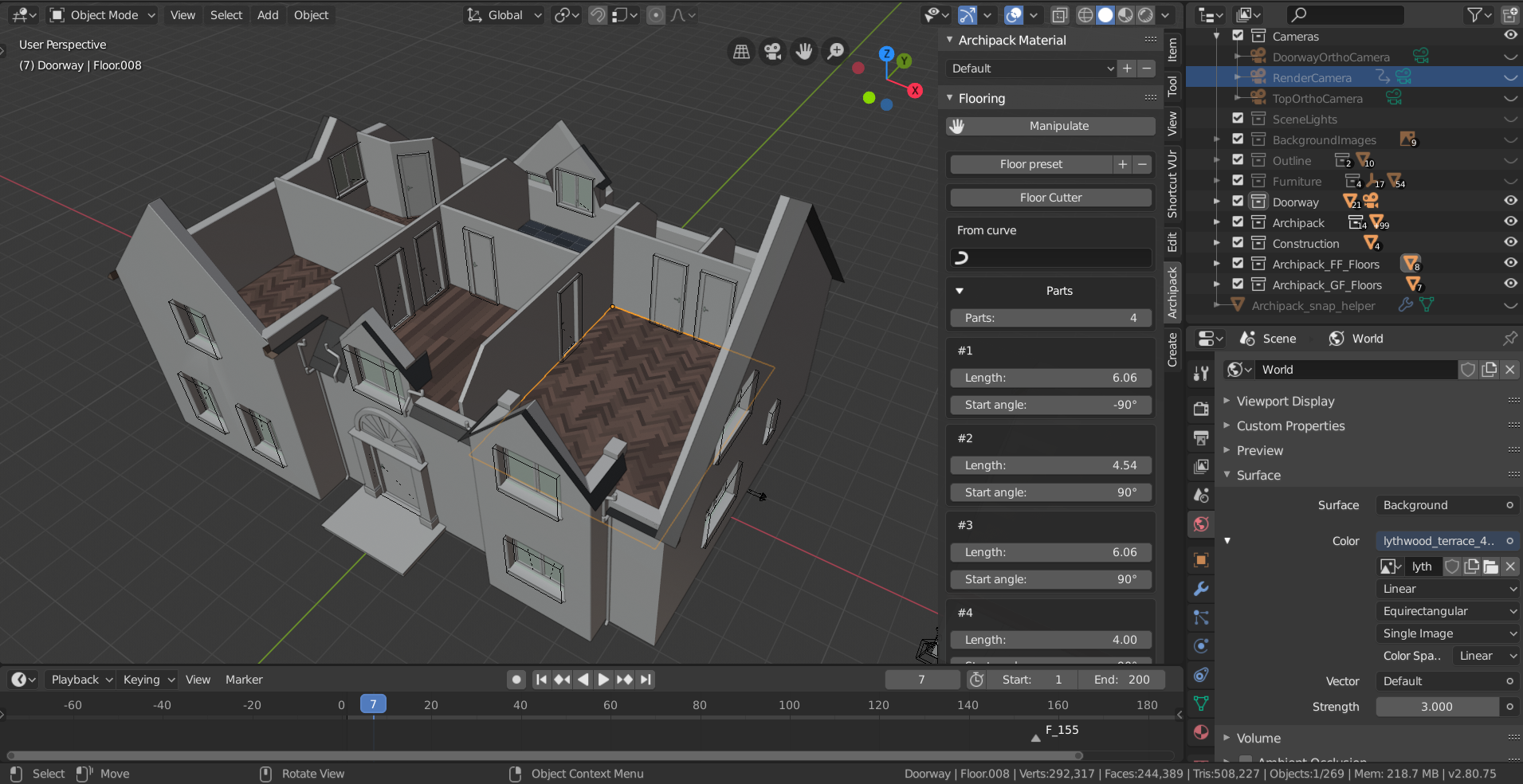
Archipack comes with loaded floors of many differing types including timber and tile. A material library in the form of a .Blend file can be downloaded from the Archipack website, and once linked within the add-on each element added to the scene will has a default material specific to its type. Adding an element without the material library will result in a default “dumb”material with material slots to hold additional material. These material slots make it easy to add your own custom material to each of the parts at a later date.
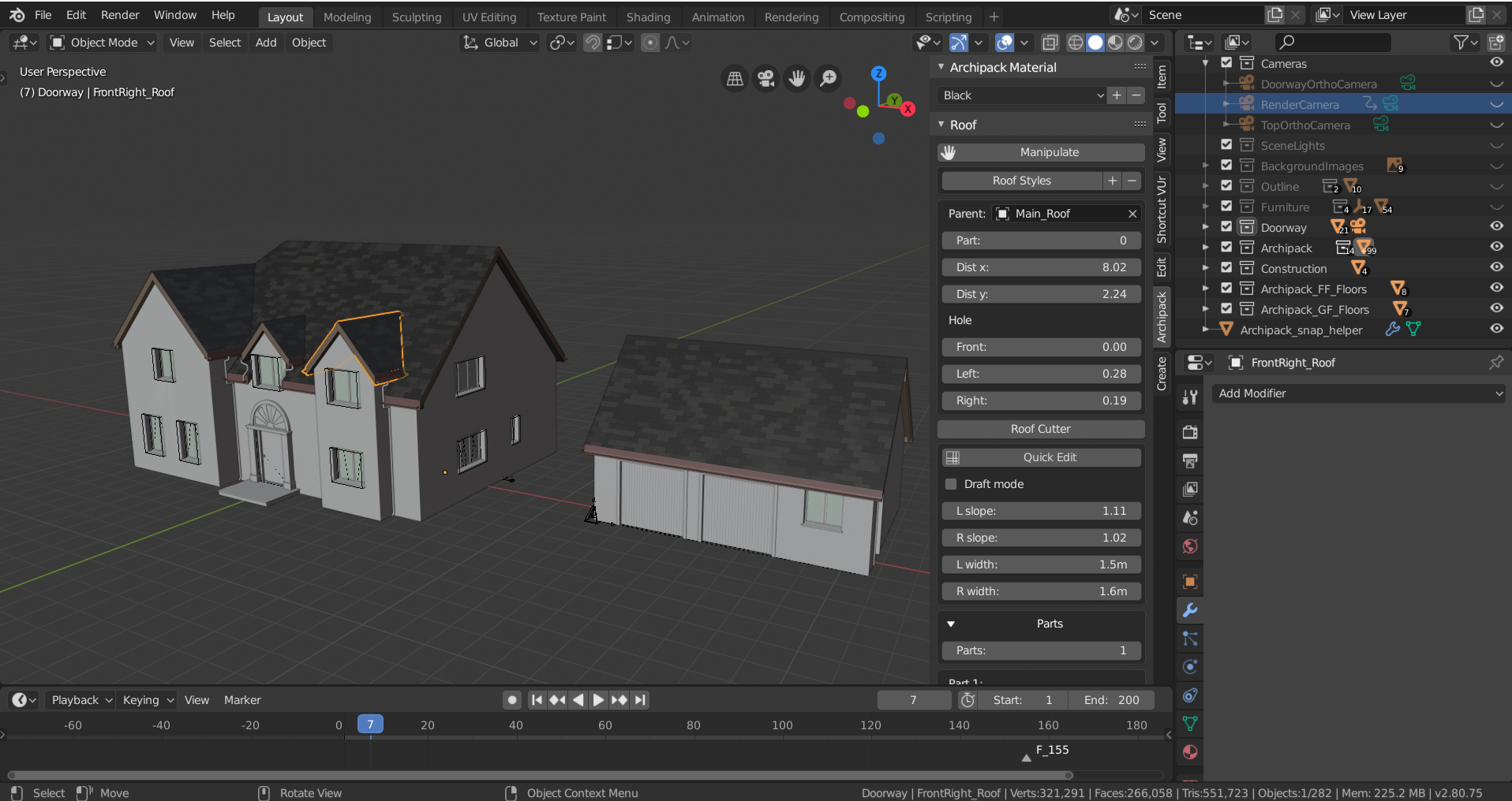
Another great feature in Archipack are the roof options available. These roofs are highly customization with a cutter option that allows you remove sections of roof. Pictured below are dormer styled roofs with the underlying roof having been cut away.
Blender has very easy to use cameras that can be easily switched from perspective to orthographic depending on your needs. When the camera is in position and is the active camera F12 will render out the image using the current render settings. The new real time render engine called Eevee can help visualize the 3D model. To use Blender’s path tracer simply switch to the cycles engine and press F12.
Taking the model a step further than the course
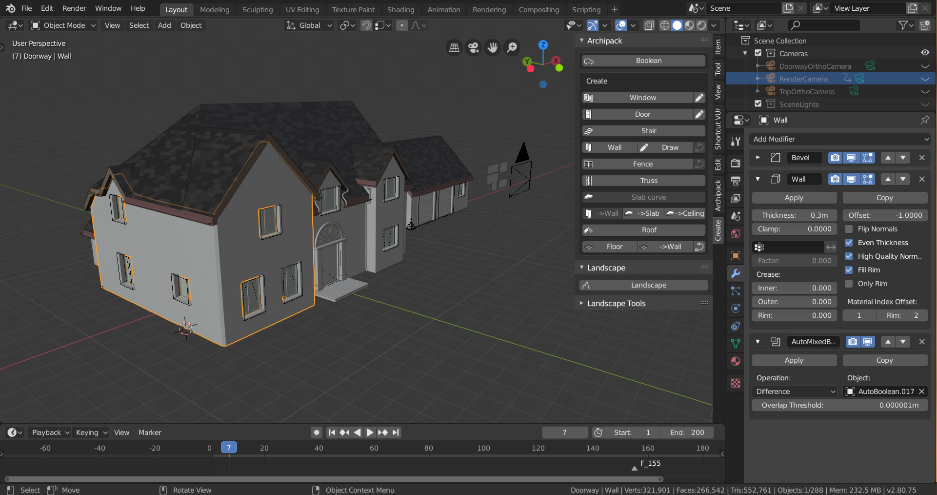
Taking this model into a game engine involves applying the modifiers, and at this stage I also clear any parent constraints. Once the modifiers have been applied the task of cleaning up the mesh begins. The goal is to replace any Ngons with quads and eliminate any other noticeable issues within the model. Combining similar objects together such as windows and doors can take place after UV mapping, that way UV maps can be overlaid one on top of another. One great feature in Blender is to link an objects UV’s from another identical object. This saves lots of time and makes combining similar objects very fast and efficient.
Exporting
Whether the model is to be used in game engines as assets or in Architectural visualization projects now is the time for final checks. Before the export begins each object should have a material and additional material slots if the object requires multiple materials.
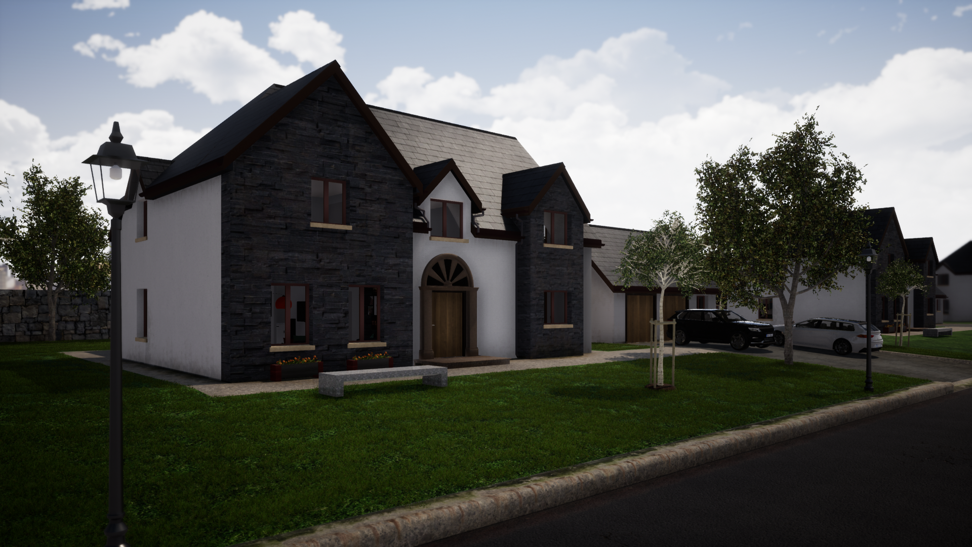
This model was imported into Twinmotion and material and environment setting adjusted to create this image.
Check out this course on Udemy here and get a discount on the advertised price!
