go to the home page
go to the page above this one – lathe – techniques
Lathe – ball-turning, spherical surfaces, concave and convex
A common problem on the lathe is turning convex and concave surfaces. A particular case of this is turning a ball. But, usually, it is not a complete ball that is required but a ball on the end of a shaft.
Among the possible methods are:
using one or more form tools,
making a round surfaces by a series of straight cuts,
using a ball turning attachment,
using linkages to control position of the cross slide.
Using a one or more form tools
Where a part of a cutting edge makes a cut on the workpiece then, where this cut occurs, the shape of the surface of the workpiece at this point will be a copy of the edge of the cutter at this point. A round, convex cutting edge will cut a concave surface. A round concave cutting edge will cut a convex surface. On a small lathe, the power and rigidity of the lathe will limit the length of the cut even if the depth of cut is relatively short.
2328 ball turning
fig using a form tool made from a piece of HSS
Very often the shape required may be part of a circle. In these cases it is possible to use existing cutters that are of the right shape. Examples of this are milling cutters.
Radius cutters can cut 90º arcs.
2326 ball turning
Cutting one way.

2340 ball turning
fig cutting the other way
In this case it is not possible to see the actual point where cutting is occurring not only because the cutting is up side down but because of the clearance angle on the cutting edge.
With radius cutters the cutter does not have any rake so does not cut as well as one might hope.
Ball ended cutters will make a cut of 90º. This is because only one side of the cutter cuts the right way. If the other side is needed then this can be done if the lathe runs in reverse. The problem here is that the height of the cutting edge vasries over the length of the arc being cut.

2341 ball turning
fig cutting using a ball ended cutter
In all of these cases it is only possible to cut with an edge of a few millimeters. If the arc is longer than this then the cutting edge has to be moved to and fro till the whole edge is cut. This means that the final curve will be slightly smaller than the cutting tool.
This is a case where cutting fluid greatly improves the cutting.
Making a round surfaces by a series of straight cuts
Any curved surface can always be interpreted as consisting of a series of short, straight edges. In practice when turning a curved surface the lengths might be quite long, say, a few millimeters. This will leave a surface that is not round enough but it can be sanded down to produce an acceptable surface.
One advantage of this method is that the diameter of the workpiece can be the maximum working diameter of the lathe..
Suppose we need to make a hemisphere D mm in diameter. The circumference of this will be 2* pi * D. But we are only making half of this which means we will only need to turn one quarter of it. At the same time the top slid is being rotated. If for each cut the top slide is rotated by 5º then the length of each cut will be:
The path of the cuts form a polygon. A circle can be made to fit on the inside or the outside of the polygon. We want it to fit on the outside so there is always metal to spare. This means the first cut is made parallel to the bed of the lathe.
It might seem that the lengths of the cuts is important but it isn’t.
This method can make round shapes only limited by the swing of the lathe It is possible to make a surface that is part of a sphere of any diameter.
One common example would be a smokebox door.
Using a ball turning attachment
A ball turning attachment is an easy way of making a round shape. Its main limitation is there is a very distinct limit as to the diameter of the workpiece as well as the angle of the surface that can be made
A ball turning attachment is really just a mechanism that cause the cutting edge to follow a circular path which is the outside of the ball being cut.
There are two different ways this can be done. The cutting edge can turn in the horizontal plane or it can turn in a vertical plane lying along the axis of the lathe..
Ball turning with cutter turning in the horizontal plane
Fitting the ball turning attachment
The whole of the top slide has to be removed.
This ball turning attachment appears to be a type “C” as made by Hardinge. It has been modified to cut larger balls than would normally be possible.
2342 ball turning
fig cross slide with top slide removed
The spigot that the topslide rotates about has to be removed.
2343 ball turning
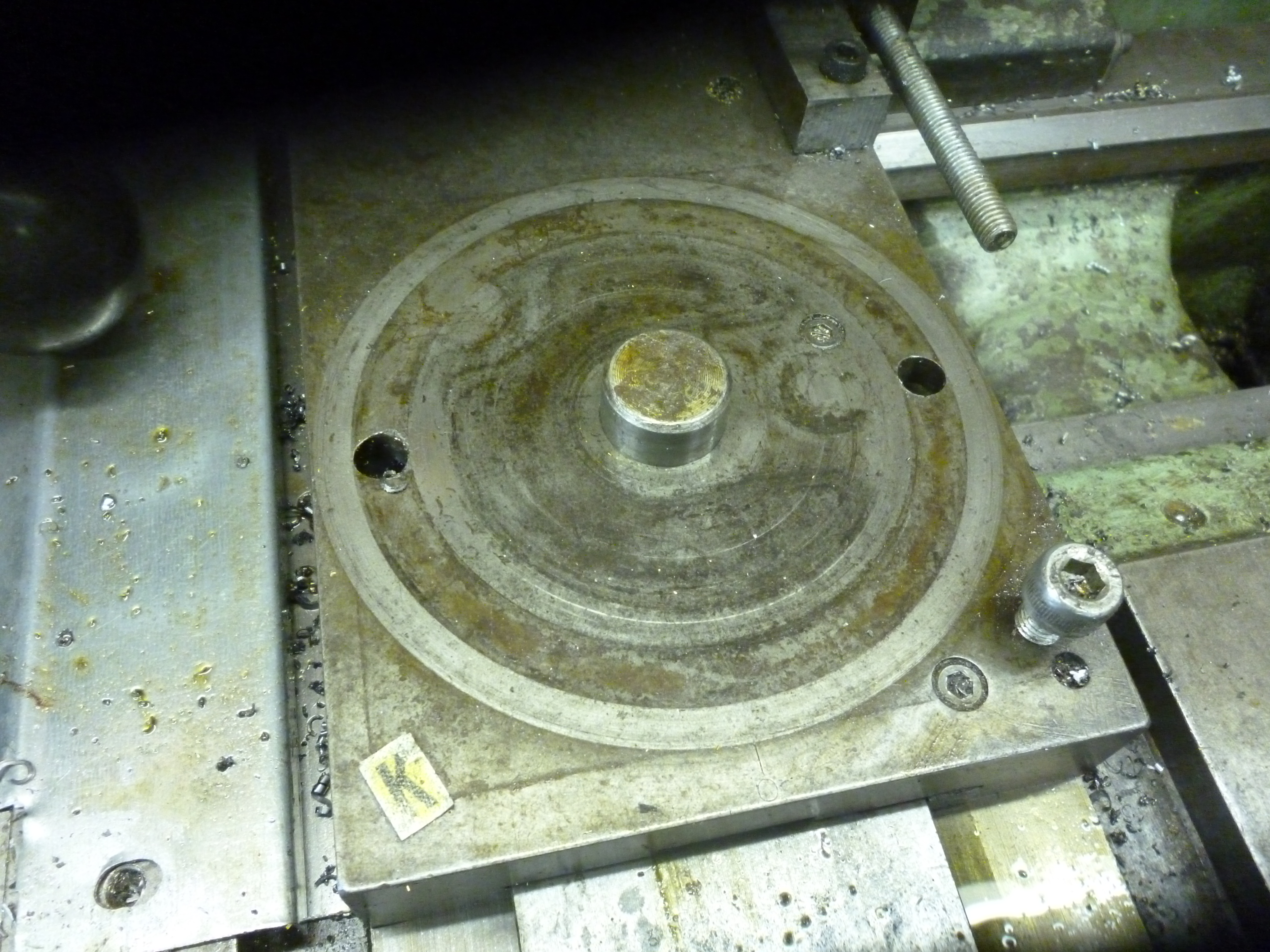
An adapter plate is fitted.
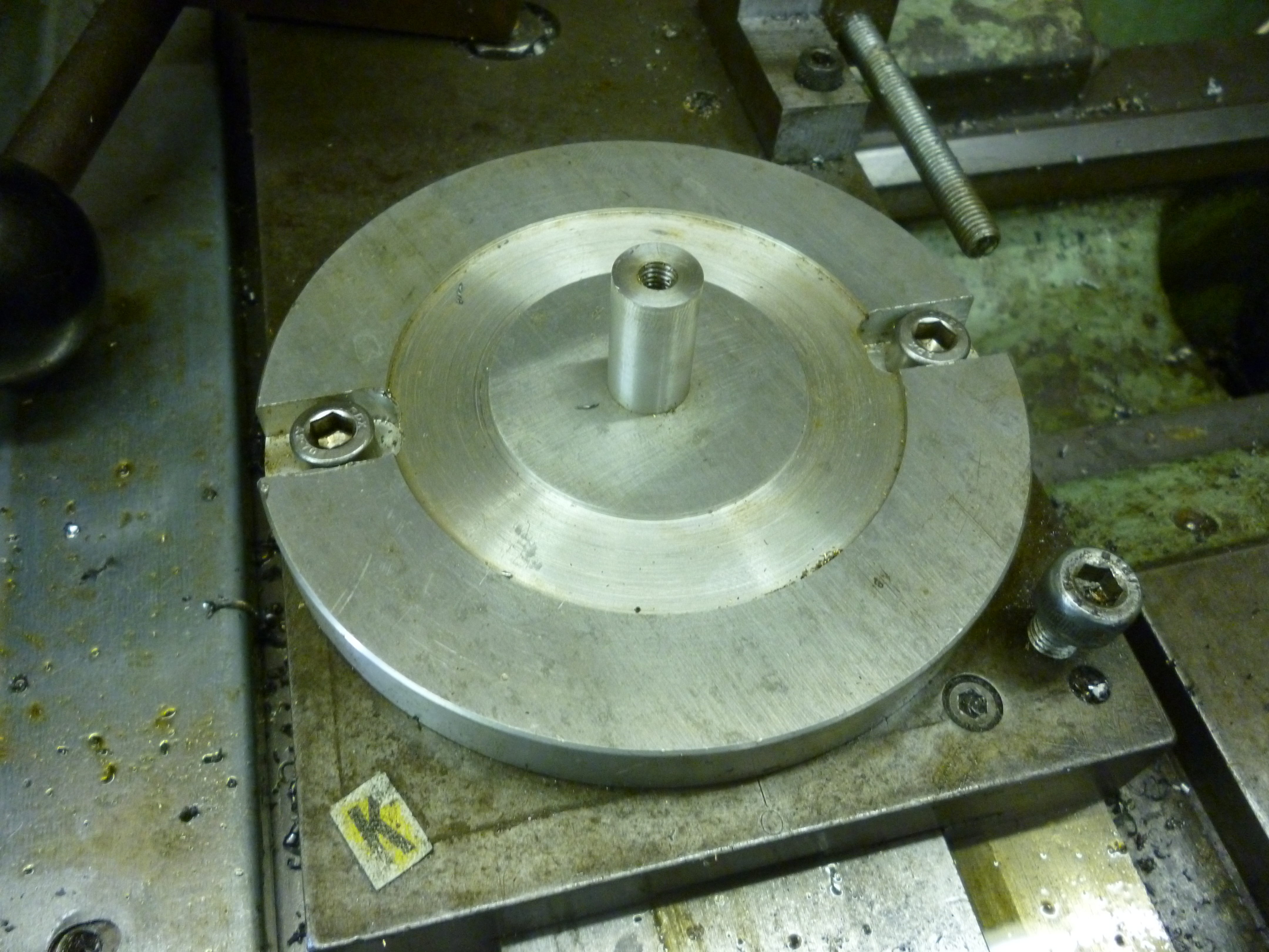
2344 ball turning
fig adapter plate fitted
This plate is fitted so it is one piece with the cross slide. It does not rotate.
Where the spigot on the adapter plate ends up is not critical. The spigot fits into a bearing in the ball turning attachment.
notice the cap screw on the bottom right side of the cross slide. This is the lock. It locks the cross slide to the saddle. It is seldom a standard fitting on a lathe but is essential for ball turning. Of course, the saddle also needs to be locked when actually cutting the ball but most lathes have a lock for the saddle.
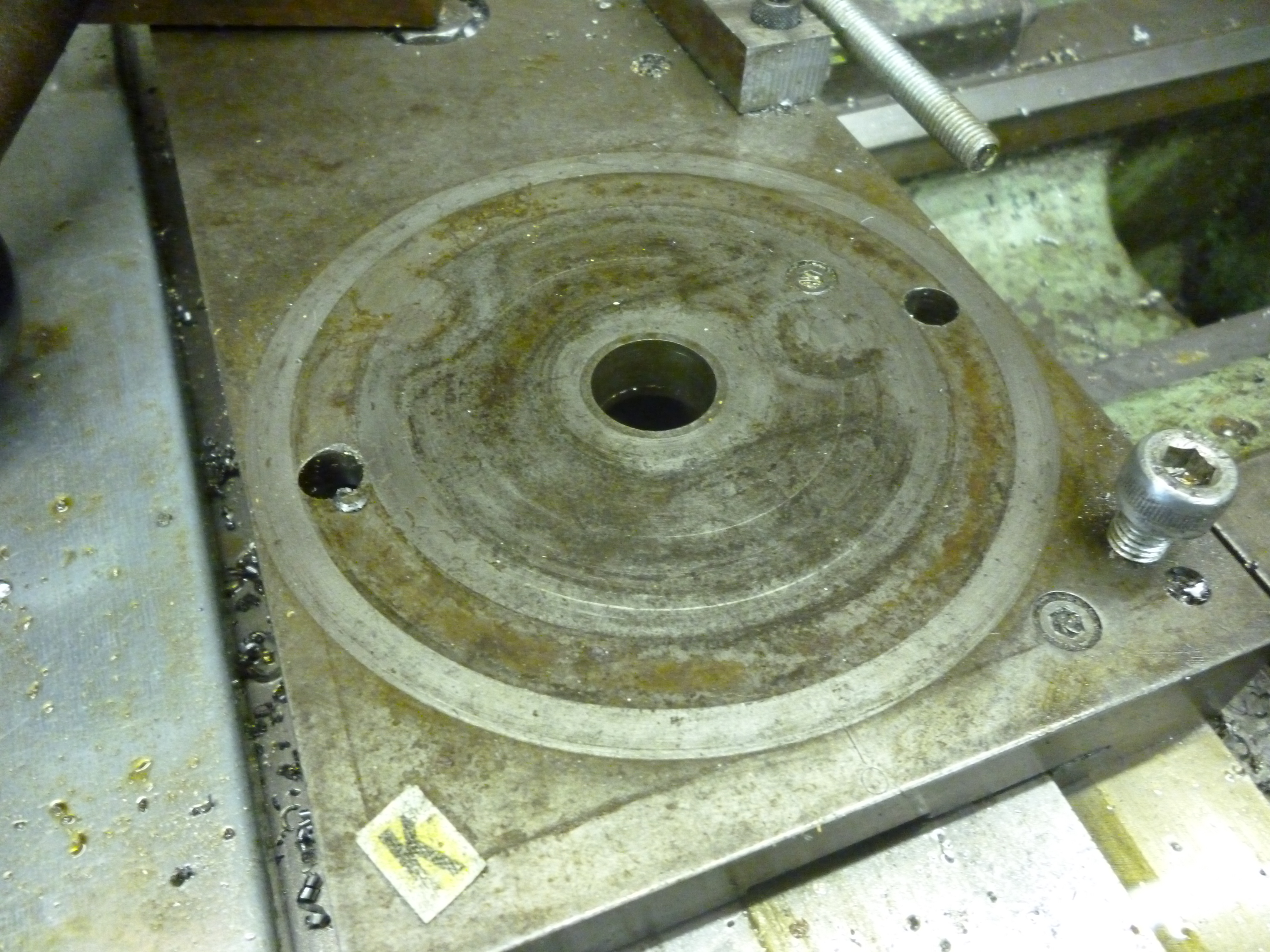
The groove is for a ring on plastic material for reducing friction.

2355 ball turning
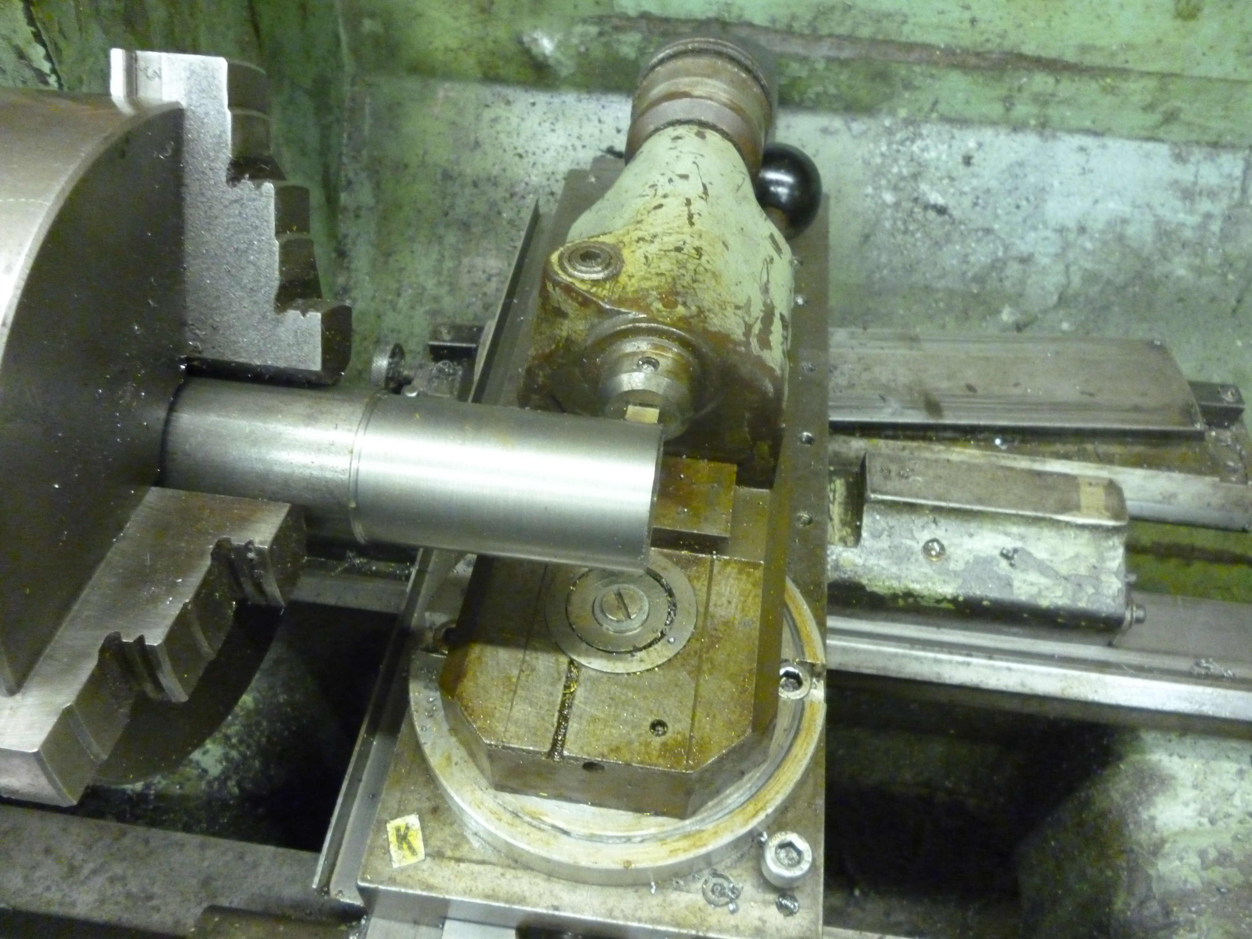
The ball turning attachment fits on this spigot.

2356 ball turning
fig ball turning attachment fitted
Ball turning attachment operation
Alignment of a ball turning attachment
To produce an accurate ball the (vertical) axis of rotation of the ball turning attachment must be in the same vertical plane as the axis of rotation of the spindle of the lathe.
For best results a four-jaw chuck or collects are needed.
Suppose the workpiece is centered in the chuck. The outside is turned down as required to the right diameter.In this case, it is important to line the attachment very carefully otherwise it might not be possible to produce a perfect ball. If a perfect ball of exactly the right size is required then one could turn the workpiece down to slightly larger than the required diameter.
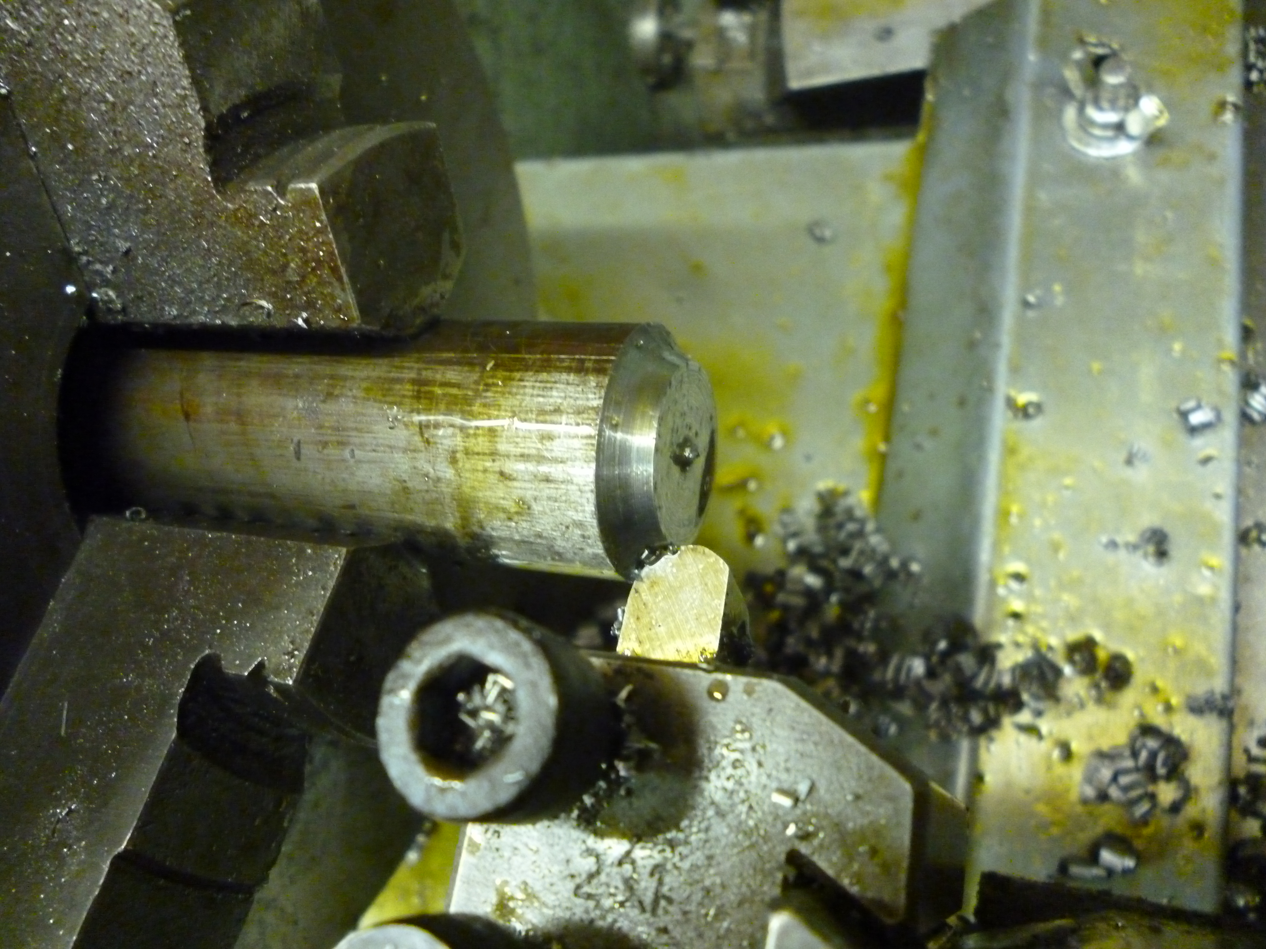
The cutter is set to just touch this on one side as shown.

2350 ball turning
fig setting the cutter on one side
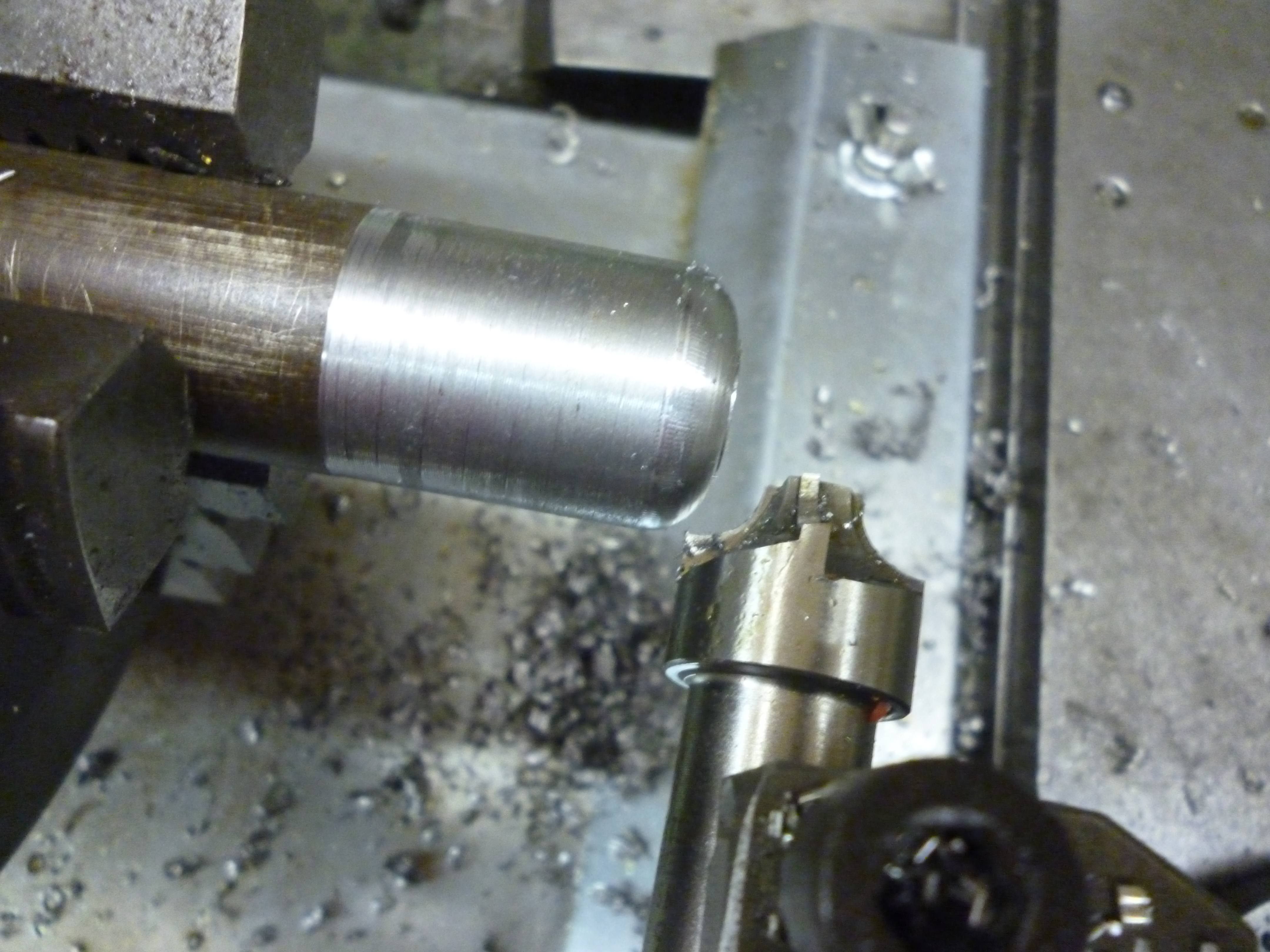
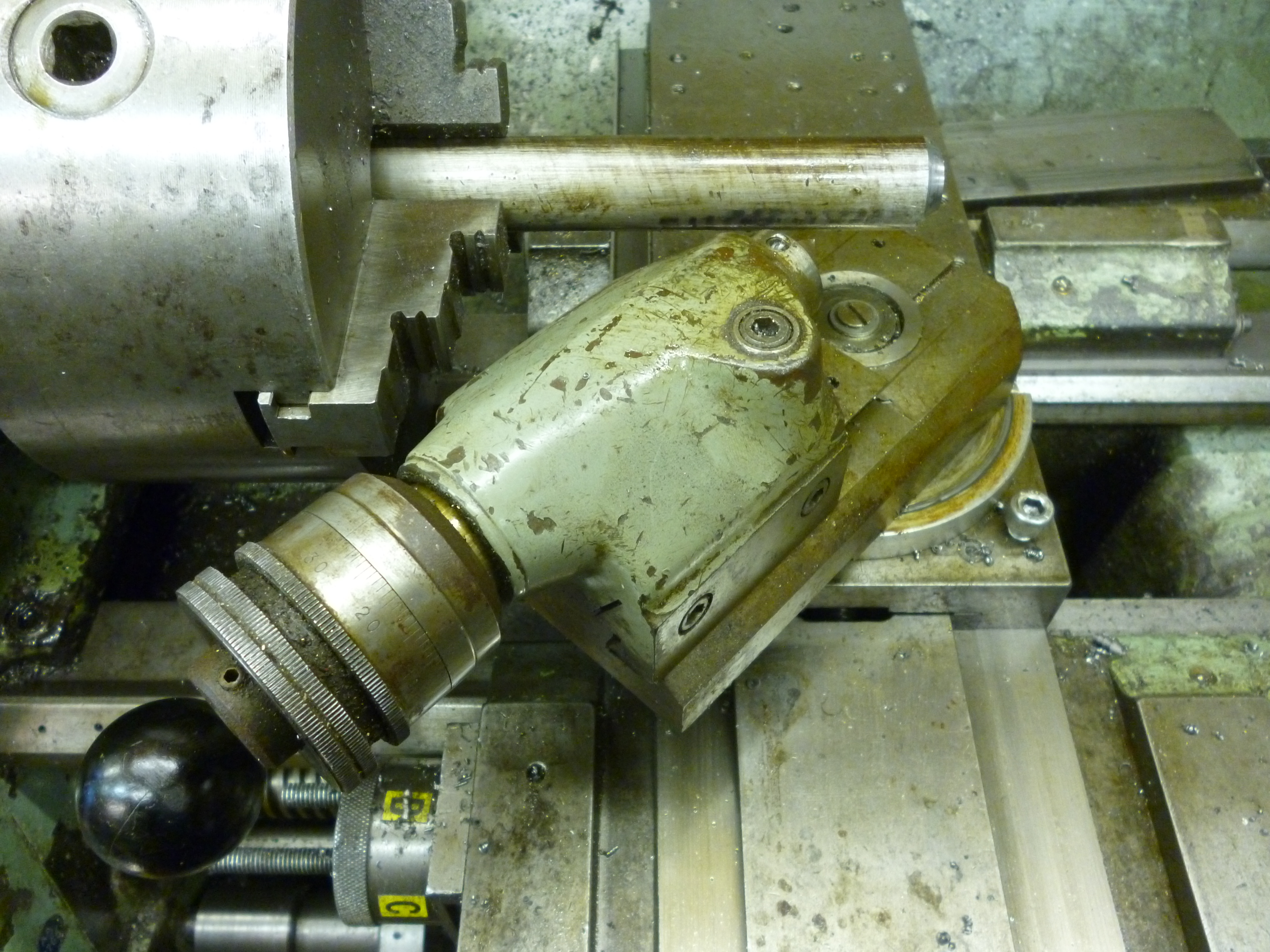
The saddle is moved right and the tool is swung round, if possible to the other side.
2351 ball turning
the position of the cutter is adjusted as is the position of the attachment in the in/out direction till the cutter just touches the surface of the bar in both positions. The cross slide is then locked.
It can easily be seen in this photo how the front of the dovetail has been cut off so as to make it possible to make slightly bigger spheres.
Having done this it is possible to set the attachment along the bed of the lathe. It is not easy to set this accurately. But in most cases it is possible to set the cutter in one of the in/out position and align the point of the cutter to the end of the workpiece. This sets the vertical axis of rotation of the attachment to the end of the workpiece. The saddle is locked. The top of the dovetail on the attachment is moved right away from the workpiece by very slightly more than the radius required. The saddle is then moved till the cutter touches the workpiece. The saddle is locked again. The tip of the cutter is now very near the last cut that will be made. The cutter is moved away from the workpiece so the first cut will just clip the corners of the end of the workpiece..

2352 ball turning
fig Setting the cutter to the end of the workpiece.
Setting the cutter
The cutter is made from a piece of square HSS. It is a simple V shape. But the V must be center of one side of the piece of HSS. The “square” hole in the attachment is slightly higher than it is wide so the height of the cutter can be adjusted as required. The cutter, made like this, will not have any rake but it will still cut.
When trying to cut a ball with the largest possible “angle” the cutter needs to have the whole of the left side cut away.
Turning whole balls
This method can make a ball on a shaft where the “angle” the ball makes is about 270º out of the 360º possible. The limit is largely the attachment hitting the chuck. It will also be noticed that to get this angle the ball has to be made a long way out from the chuck. To get the best possible result the left side of the cutter needs to be removed.
2346 ball turning
fig showing the limit on “angle” of ball
Using linkages to control the position of the cross slide
If a linkage can be fitted to the bed of the lathe at one end and connected to the cross slide at the other end then if the cross slide is moved this linkage will make the saddle move left/right so the cutter moves in a circular manner.
The forces on the linkage are such that only relatively large radius’s can be cut using this method.
The point that the linkage pivots about on the bed of the lathe will determine the position of the center of the arc the tool moves in. The radius of the surface produced will be determined by the length of the link plus the radial distance of the cutting tip from the path the link on the saddle takes.
The diameter of the workpiece is limited by the swing of the lathe. For a convex surface the link is on the left of the saddle. Since the workpiece will be just to the right of the chuck the radius that can be cut varies from next to nothing to the distance from the left end of the bed of the lathe to somewhere just to the right of the chuck.
The linkage has to be fitted on the bed so its center is directly below the axis of rotation of the spindle otherwise a part of a doughnut will be formed.
Ball turning with the cutter moving in the vertical plane
The usual way of doing this is to make the attachment so that it fits the tool post. The cutting part is on a dovetail slide. The position of this determines the diameter of the cut. In the example shown below the dovetail part was taken from a small dividing head.
Linkages used to make concave surfaces
If the linkage is to the right of the saddle the surface will be concave. The length of the linkage can be from next to nothing to the distance between the right side of the saddle to the end of the bed of the lathe.
Limit on using linkages
When using a linkage as described above one limit is that it will only work if the cutter is moving at an angle to the workpiece of not more than about 30º. This means that only parts of a sphere can be turned like this.
