

Mac-to-VGA Composite Sync-Splitter Progress
I’ve been continuing the design development on a Mac-to-VGA video adapter with an integrated composite sync splitter, whose concept was first discussed in October, with a first-generation prototype following shortly after. To recap: some Macintosh models like the Mac IIci and IIsi and some Apple video cards like the Toby card output a composite sync signal, instead of the more common configuration with separate horizontal and vertical sync signals. VGA monitors don’t have a composite sync input, but some monitors will accept csync if it’s connected to their hsync input. For VGA monitors that lack this feature, the IIci/IIsi/Toby/etc simply won’t work, no matter how the DIP switches are configured on a passive VGA adapter.
My goal is to design an active Mac-to-VGA video adapter with the ability to process an incoming csync signal and generate new signals for hsync and vsync, thereby enabling the IIci/IIsi/Toby/etc to work on standard VGA monitors and LCDs. This sync translation should be optional, so the adapter can also be used similarly to a standard passive Mac-to-VGA adapter, and it can support the widest possible variety of computers, video cards, and video modes. I’m happy to report that I’m very close to this goal.
An active adapter needs a power source, and the first challenge of this development effort was that the Macintosh video port doesn’t provide any power. The port only has ground connections and data signals, but no handy +5V supply pin. I’ve settled on a design that uses phantom powering, drawing current from the sync input signals themselves in order to power the adapter’s circuitry. While this is generally considered a bad design practice, I’ve been able to keep the adapter’s total current consumption low enough that phantom powering doesn’t interfere with the normal functions of the sync signals. I prefer this solution over requiring an external power source, since it enables the active adapter to be used identically to passive adapters. Just plug it in to the video port, and it works.
The first generation prototype used an LM1881, a specialized sync-splitting chip that can generate a new vsync signal from a csync input. The LM1881 can’t generate an hsync signal, however. This prototype worked with some monitors that I tested, but not others. I considered replacing the LM1881 with other more advanced sync-splitting chips, but they’re more expensive and more rare. After some experimentation I decided to use a small microcontroller instead of a dedicated sync-splitting chip, since it would be more flexible, cost less, and consume less power than a dedicated sync splitter. That decision was the foundation for this second-generation prototype, which I’m tentatively calling the Mac Sync-inator.
Generation Two: VGA Mac Sync-inator
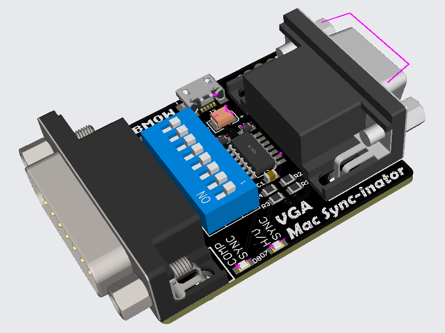
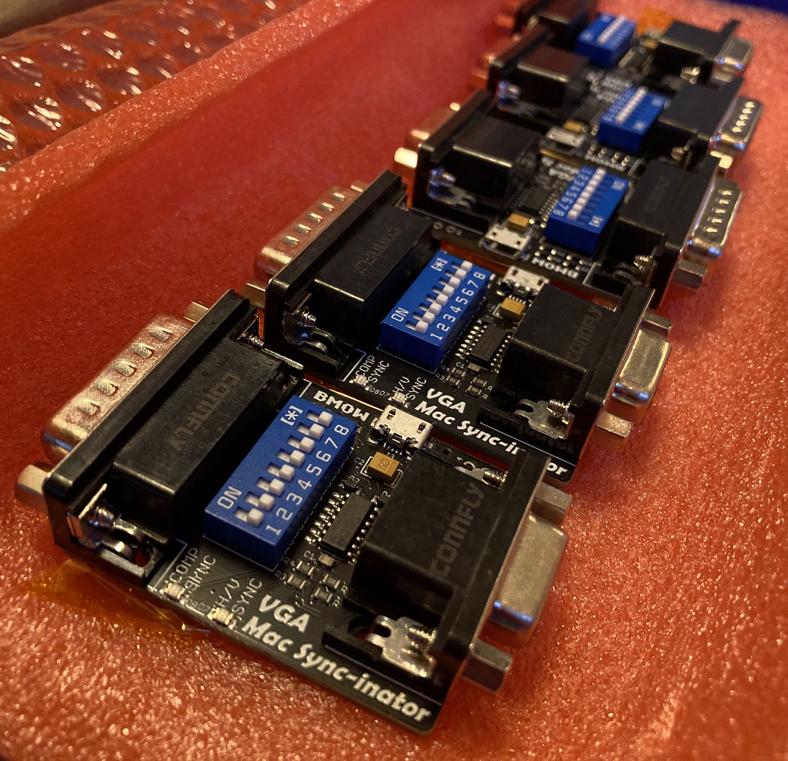
Here’s a 3D rendering of the prototype. There’s not much to the hardware: just a DB-15 for the Macintosh side, an HD-15 for the VGA side, an ATTINY404 microcontroller, and a set of DIP switches. There’s also a USB jack for an optional source of external power, although so far my tests have found it isn’t needed. A pair of LEDs light up to indicate whether the Mac is outputting composite sync, separate horizontal and vertical sync, or both. This is a valuable debugging aid when you’re staring at a black screen and aren’t sure which piece of equipment to begin troubleshooting.
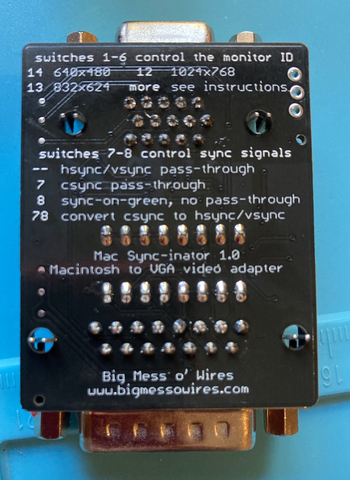
The first six DIP switches configure the monitor ID sense code that the Macintosh will see, and they function very similarly to the DIP switches on passive adapters. Many older Mac models check the sense code at startup, and use the code to determine what resolution of video output to generate, or whether to generate any video output at all. The last two DIP switches control the microcontroller’s sync conversion behavior. There are four choices:
- Pass through hsync and vsync without any conversion – For newer Mac models that already output separate hsync and vsync signals.
- Pass the Mac’s csync signal to the monitor’s hsync input – For older Mac models attached to VGA monitors that can accept a csync signal.
- Don’t pass any sync signals – For Mac models and video cards that have sync information included in the green video channel, called sync-on-green.
- Convert the csync signal into new hsync and vsync signals – For older Mac models attached to any VGA monitor, with the widest compatibility.
It’s that last option for csync conversion that’s the interesting one, and that makes this adapter unique. Passive adapters can do the first three behaviors, but not composite sync conversion.
And it works! Using the Mac-Syncinator in csync conversion mode, I’m now able to run my Macintosh IIci on any of my monitors, including the ViewSonic VG900b that has consistently been the pickiest monitor through all my development efforts. Hallelujah!
If you’ve ever used another Mac-to-VGA adapter with a set of DIP switches, then you’ve surely had the experience of not remembering what all the DIP switches do, and not being able to find the manual when you need it. It’s frustrating. To help with this problem, I’ve included a list of the switch settings for the most common video modes directly on the back of the Sync-inator:
Remaining Work
So what’s next? Is it all finished? Not quite. As of right now the Sync-inator works with the composite sync signals from the Macintosh IIci and IIsi, and from the Apple Macintosh II Monochrome Video Card 661-0518. But it doesn’t work with the Toby card (Macintosh II Video Card 820-1098) nor with a SuperMac ColorCard SE/30 that I tested. The reason is that not every composite sync signal is constructed the same way.
Here’s the csync signal from the Mac IIci, along with the new hsync and vsync signals that are created by the Sync-inator:
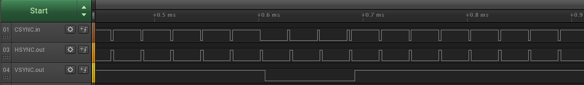
The csync signal is normally high, but there’s a short low pulse after every horizontal scan line of video. Once per frame, the polarity of the whole signal is reversed for a few lines – this inversion is the vsync. The important detail is that falling edges of csync are always regularly spaced, even during the inverted vsync period. The Sync-inator’s microcontroller uses these edges to derive timing information and create a synthetic hsync signal to feed to the monitor.
Now contrast this with the csync signal from the Apple Toby card:

During the vsync period, the csync signal polarity isn’t reversed – it’s simply flatlined at zero so there’s no timing information the microcontroller can use to generate synthetic hsync pulses. The falling edges of csync aren’t always regularly spaced either. They’re mostly consistent, but during the lines just before and just after vsync you can see the csync pulses are suddenly twice as frequent as normal.
The SuperMac card has the same flatlined zero behavior as the Toby, but not the double-speed csync pulse behavior.
The double-speed csync pulses seem like maybe they could be filtered out by ignoring any csync pulse that arrives too soon after that previous pulse. But what’s “too soon”? If I could assume a specific video resolution then I could probably use a fixed time duration for the filter, but if the video resolution might change then I probably need to measure the normal duration between pulses and then create a dynamic filter threshold based on that. Even if I knew exactly how long to make the filter, I’m not yet sure how I would implement it, since csync is triggering a hardware peripheral in the microcontroller rather than being polled and processed by generic program code.
I’ll probably focus on the flatlined zero problem first, since it’s common to both video cards. In theory the microcontroller needs to measure the average time between csync pulses, and detect cases where a csync pulse doesn’t arrive within a small error window around the expected time, and then insert a synthetic pulse in place of the missing pulse. That might be plausible if I were using a super-fast microcontroller and all of this behavior was implemented in program code, but I’m relying heavily on hardware peripherals in the chip. Those peripherals can’t necessarily be configured for that type of complex behavior. Maybe I can rig up some clever scheme of enabling and disabling interrupts at certain times, where the interrupt handlers change the hardware peripheral states, to create a behavior for a missed csync pulse. There will necessarily be timing jitter in these newly-created pulses though, plus some delay between the end of the window where csync was expected and the start of the time where the synthetic pulse is generated. From my earlier experiments, many monitors don’t react well to this kind of jitter and variance in the sync signal timing, so this whole approach may not even be viable. I guess I’ll find out.
It may be impossible to support these oddball csync formats, and I may have to footnote the Toby and ColorCard SE/30 as *not compatible with csync conversion. That wouldn’t be too bad, since the main goal was Macintosh IIci and IIsi support, which has already been achieved. But I’ll give it my best effort!
Read 15 comments and join the conversation15 Comments so far
Leave a reply. For customer support issues, please use the Customer Support link instead of writing comments.
I’ve got a partial solution for the flatlined zero problem, which will generate extra hsync pulses if they’re needed during vsync. Let’s see if I can explain this so that it makes sense to anybody.
I’ve configured a second hardware timer so that it only counts while the csync input is low. This is a hardware feature, and is accurate to within one clock cycle. The period of the timer is the duration of one scan line at 640×480 resolution. Whenever csync is high, the hardware pauses the timer, and my code resets the timer value to zero. So the result is that now I have a hardware based timer that measures how long csync has been low.
This timer never reaches its maximum value during the visible part of a video frame, or during the vsync period for normal computers like IIci, because csync always goes high before the max value is reached. But on the Toby card and the ColorCard SE/30, during the flatlined zero vsync period, the timer will eventually reach its max count. I have code that polls for this condition and manually triggers another single-shot timer to generate an extra hsync output pulse. After some fine-tuning, this is working fairly reliably.
Some problems with this method:
– The timer is hardware, but I’m still using software to poll for the max timer value and trigger a new hsync pulse, so there’s considerable jitter. It seems good enough in limited testing, but less jitter would be nice.
– The timer’s max count value was set based on experimental testing with one specific microcontroller. I’m using the built-in RC-based clock on the microcontroller, which is only accurate to within a few percent. So the timer values that work well on this particular microcontroller might not work as well on another sample.
– The timer max count value is hard-coded for 640×480 video. At higher resolutions the scan lines come more frequently than 640×480, so these extra hsync pulses controlled by the timer will have the wrong frequency. That’s not so bad though – 1024×768 composite sync with a flatlined zero behavior wouldn’t have worked before this, and it still doesn’t work now, so at least I haven’t made anything worse. And 1024×768 with composite sync that *doesn’t* have the flatlined zero behavior will continue to work, because the timer max count value will never be reached.
– If I used a different hard-coded timer value, I could make 1024×768 work but then 640×480 wouldn’t work. If I could dynamically measure the horizontal rate and determine the actual video resolution, that would be ideal, but it isn’t simple. I’ll probably stick with a hard-coded value for 640×480 since it’s the most common resolution.
– 512×384 composite video will be broken by the addition of this timer. Because the horizontal lines will come more slowly than 640×480 lines, the timer will always reach the max count and it will insert extra hsync pulses where they shouldn’t be. That’s bad.
TLDNR – I have a solution that mostly works for 640×480, although perhaps it’s not completely robust, and that’s effectively a no-op at higher resolutions (no better, no worse than before), but that breaks 512×384 video in all cases.
According to Apple’s specs, the Toby card only does 640×480. The SuperMac card specs I can find aren’t official (Gamba’s site), but only note 640×480 as well. Since it breaks other modes, the generated h-sync pulses likely should only be enabled with the 640×480 sense code.
The SuperMac card comes in many varieties, but most will do additional resolutions beyond 640×480. The particular SuperMac card that I have also does 1024×768 as well as some other resolutions I haven’t tried like 640×870. So there’s at least some need for extra hsync generation in video resolutions beyond 640×480.
Unfortunately the Sync-inator microcontroller has no way of knowing what monitor ID sense code is set on the DIP swtiches – the code is configured by simple switches connected directly to the SENSE0/1/2 pins on the Mac video port. But even if the MCU knew the selected sense code, that doesn’t necessarily determine the actual video resolution. The sense code is more like a “request” to the Mac’s video hardware, which it may ignore. The Mac IIci and IIsi use the sense code, as well as some other Apple video cards. But the Toby ignores it and always outputs 640×480, while the SuperMac card ignores it and outputs a resolution that’s software-selectable from a control panel.
The only foolproof way to address this would be for the microcontroller to measure the actual horizontal scan rate, and adjust accordingly. But failing that, I would be OK with a solution that works for inserting extra hsync when needed at 640×480 and that has no effect at other resolutions. The need for extra hsync on composite video cards with resolutions beyond 640×480 is like a niche case within a niche case. 1024×768 composite sync would still be handled appropriately, so long as it’s “normal” composite sync like what’s generated by the Mac IIci and IIsi. It’s only the case of 1024×768 with the flatlined zero vsync behavior where there’s a potential concern.
For the Toby, does anyone remember the MaxAppleZoom extension that would make it display more pixels on the 13″ Apple display? It was magic… like a hardware upgrade done totally through software. I used it on my Iicx. This: https://apple.fandom.com/wiki/MaxAppleZoom
It’s maybe another magical edge case you might want to think about. Thanks for documenting your progress!
Let’s think about what the h- and v-sync pulses were originally designed to do, and why there is a “sync” in their names.
I’ll ignore color, because television started in black and white, and color is not relevant for sync pulses.
If you want to control a bare cathode ray tube connected to some hardware, there is a much easier way than sync pulses to control the electron ray position. Just use two voltage or current signals directly controlling the X and Y deflection plates / coils. This is what happens when using an analogue oscilloscope in X-Y-mode, and digital oscilloscopes usually can emulate the X-Y-mode. A third signal controls the blanking input of the oscilloscope and thus the brightness. (This input got lost over the decades.)
So, why don’t we use oscilloscopes in X-Y-mode on our vintage computers? Simply because TVs (and monitors for security cameras) were much cheaper.
That leads to the question why TV does not use X and Y position signals. TV has a long story of restricted resources, mainly available bandwidth and cost limitation for the TV receivers. Getting rid of repeated signals by some clever tricks solved the bandwidth issues.
Using mains voltage for the Y (vertical) signal could have been a way, 50 to 60 Hz are quite good for generating a seemingly stable image (instead of a running dot), but mains supply nets may get split and run async from each other. So, the vertical signal inherited just the mains frequency, but is not synchronous to the mains voltage.
The TV solution is to have an oscillator running in the receiver at about the frequency of the sender’s vertical signal. To get a stable image, both oscillators have to be synchronized. A short pulse is sufficient. Because the electron ray has to move back from bottom to top, there is some time in which no image is transmitted. That time is used for sending the vertical synchronisation pulse.
The horizontal oscillator works almost exactly the same. The receiver runs an oscillator that is synchronized to the sender’s oscillator by a short pulse. A little bit of extra time is again used to send the horizontal sync pulse within the image information.
That trick completely eliminates the need for separate H/X and V/Y signals, and just needs a little bit of time without a visible image in the image signal.
Now, what happens when one of the sync pulses is lost due to radio interference? Not much at all. Both the H and the V oscillators just keep running. Yes, they will drift over time, but a few missing pulses won’t hurt at all.
Everything after black and white TV is just stacked on top of that: color, stereo, teletext, 16:9 aspect ratio, all PC and Mac video signals.
And that also explains why the two graphics cards can get away with omitting the h-sync pulses for a while. They are not needed. The H oscillator in the monitor will just keep running, and sync again once the h-sync pulses return.
Now guess. This is what your microcontroller needs to do. Have at least one oscillator running synchronous with the Mac’s H oscillator. You need a PLL.
I think it should be possible to use a hardware timer and sync it to a relatively slow (10s of kHz) external clock signal. If the HW timer is too fast, its pulse will arrive shortly before the external pulse, and you need to slightly slow down the timer. If the timer’s pulse arrives shortly after the external pulse, you need to slightly speed up the timer. If there is no external pulse within a reasonable number of clock cycles of the HW timer, you are in the missing H-sync phase of those graphics cards and should not touch the HW timer speed.
Tux2000
I do remember MaxAppleZoom, it was something like 20 extra pixels horizontally? Magic indeed. I’ll need to dig it up and try it. I would guess it doesn’t change anything about the sync signal rates, it simply outputs a few more pixels on each line and has a correspondingly shorter hblank period.
This little ATTINY chip has many very clever hardware features, but unfortunately nothing like a hardware PLL. A software-controlled PLL might be doable, but I think I’ve found another solution. The chip has a timer mode that’s specifically designed for measuring the frequency and pulse duration of an input signal, so I can run that for about 100ms milliseconds to gather information about the csync input and then decided how to proceed. This is enough data to tell me not only the horizontal scan rate, but also whether there’s any csync activity during the vsync period (the flatlined zero problem) and whether there are double-speed csync pulses before and after vsync. I still need to iron out many details, but I think this may be enough to get EVERYTHING working at any video resolution and combination of csync behaviors.
The last tricky bit is how to trigger the generation of an extra hsync pulse (single-shot timer B) based on the internal timer A state. Right now I’m polling timer A in software and using it to manually trigger timer B, which works but introduces some jitter. An interrupt might be better, it would still involve some delay but the delay should be more predictable and consistent. I need to search for a hardware method to connect the two timers in the desired way. If it’s not possible, I think my software method is passably precise enough for the monitors I’ve tested.
Sync-inator is pretty good…. There’s also NSYNC (the music group) riff in there somewhere too
Hi,
I seem to remember that the EVENT system on the ATTiny404 can use one timer to reset/influence another so that part of the datasheet might be worth a look.
However, a software PLL would consist of the ICP (Interval Capture Peripheral) that you’ve found for measuring frequency, a divider (which can be done in a couple of clock cycles on the ATTiny404) and a bit of code to process the error. My understanding of your architecture suggests that you’re not far off that but have some extra details that might be simplified.
You’d have one PLL plus a hardware timer for each of h-sync and v-sync. The two soft-PLLs could share the ICP peripheral.
Glad someone is working on this problem, juggling sync is half the battle these days for anything analogue/retro- I can’t wait to get one of these and hook it up to my OSSC and make a Mac profile for HDMI output!
You don’t need a sync splitter for the OSSC. It can natively handle sync-on-green and composite sync video out of the box.
I’m still actively working on this, and it’s still “almost done”. The step between almost done and completely done is proving to be harder than I’d thought.
I’ve tested with MaxAppleZoom and it works.
The latest version is using the microcontroller’s programmable combinatorial logic units as well as the event system in order to handle as many details as possible asynchronously. This eliminates most jitter and variability in the generated hsync/vsync signals when splitting a composite sync input signal. But it’s not perfect and I’m still running into a few cases where a specific monitor doesn’t like my software-generated sync signals from specific video sources. It’s turning into a game of whack-a-mole trying to find and fix these without introducing new issues at the same time.
The good news is that the Sync-inator will be able to do everything that standard Mac-to-VGA adapters do, plus a bunch of extra stuff too. The only slightly bad news is that it might not be able to handle every example of “extra stuff” that I’d hoped it would, and there may be some video card / monitor combinations that don’t work on standard adapters and don’t work on the Sync-inator either.
My goal now is to address as many of these cases as possible, but as you can probably imagine it’s very time consuming. I now have nine monitors crowded around my desk, with 10 different video sources, many of which support multiple graphics resolutions. I have a test matrix for all those combinations, and whenever I change anything then I need to start over again with all the testing.
MaxAppleZoom in 2024… wow. You’re a magician, as if we didn’t know that already from your other creations!
MaxAppleZoom produces some really odd resolutions and refresh rates, like 704×480 at 62.4 Hz. But who could say no to 10 percent more screen width?
Just thinking out loud:
If you need two (or more) conflicting configurations of the ATtiny to support standard stuff and some exotic combinations, you could add one or more switch inputs to the ATtiny, read them on startup, and configure the ATtiny for standard or exotic combinations. The ATtiny404 has a 10-bit-ADC, so you should be able to read up to about 8 bit from a single pin using a resistor divider. That should be more than sufficient for a lot of exotics, probably more than you can fit into the flash memory.
What MaxAppleZoom did wasn’t all that unusual for the time period. There were tons of programs on the PC side that reprogrammed VGA chips to output some really oddball resolutions, many of which don’t work on modern displays.